How to use I2S along with 8-bit parallel bus

Xavi92
Posts: 45
Joined: Thu Mar 28, 2019 2:26 pm

How to use I2S along with 8-bit parallel bus

Postby Xavi92 » Thu May 23, 2019 3:00 pm

Hi there,

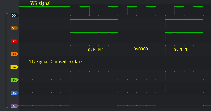
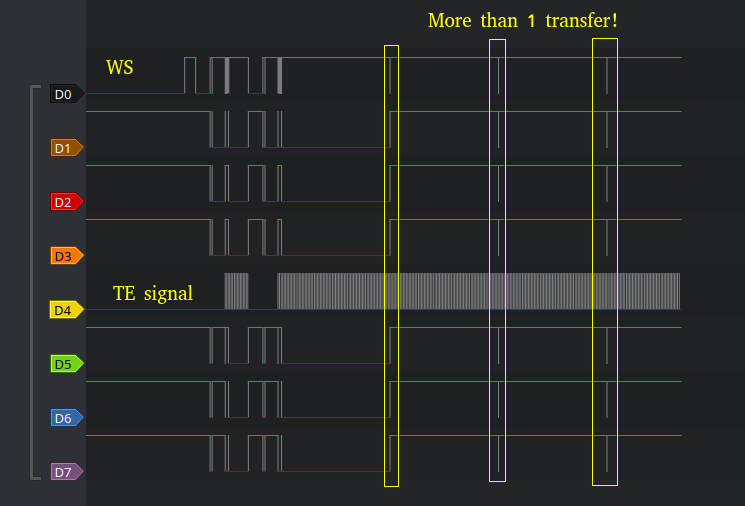
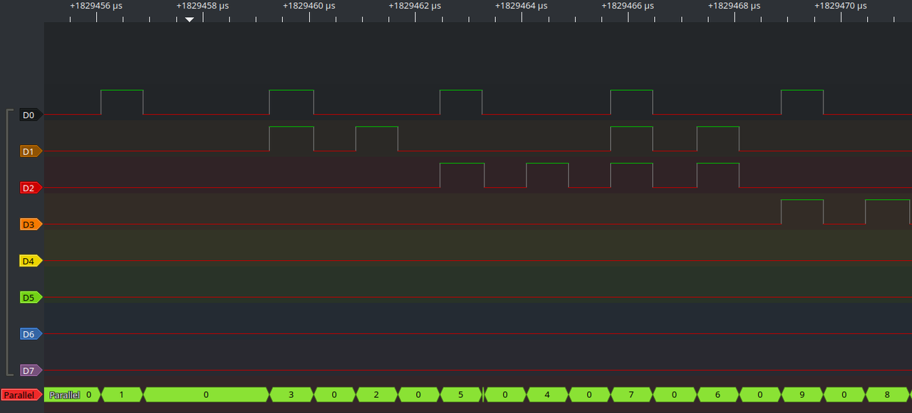
For some weeks now I have trying to interact with a ILI9481-based TFT screen with no much success so far. My intention is to use one of the available I2S peripherals to send the following signal:

Image

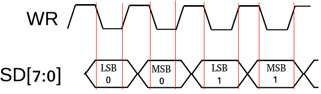
Since the LCD uses 16bpp format, 2 WR clocks per pixel are needed.

I wanted to write my own driver for this, based on the example provided here. This is the approach I took:

1. An external module prepares a 4092-byte buffer (largest word-aligned allowed size given ESP32 DMA limitations) and calls i2s_draw().
2. i2s_draw() sends the buffer over I2S and sets an internal status flag (defined as _Atomic to avoid data races).
3. The external module prepares another buffer of same size while I2S is working.
4. i2s_isr() is executed when the buffer has been sent and it clears the status flag so the external module knows I2S is available again.
5. The external module sends the second buffer over I2S and goes back to step 1 until the whole screen is completely drawn.

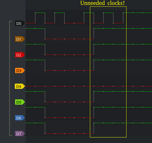
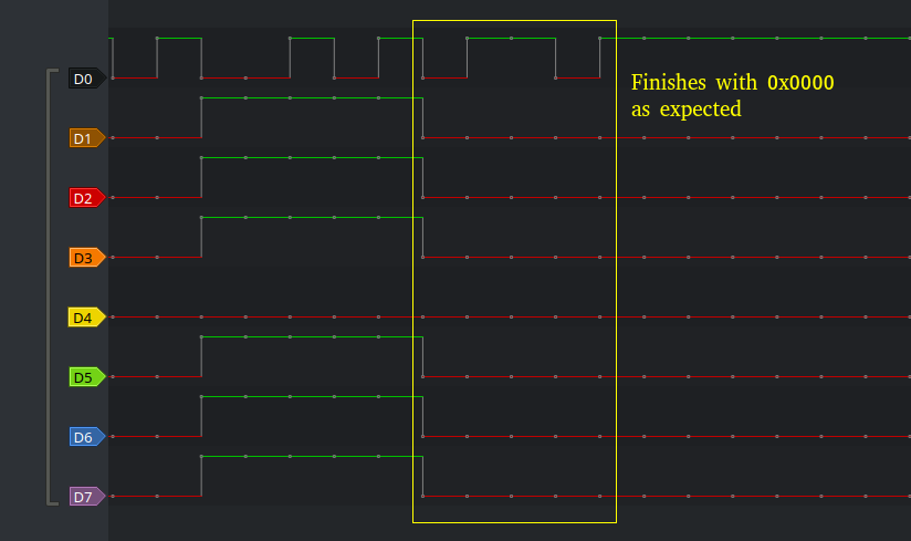
I wanted to keep things simple for the time being, so I avoided dynamic allocation, complex structs (as the ones used by esp-idf component i2s) and FreeRTOS' artifacts as much as possible. The screen does get painted, but not as expected e.g.: I2S would only send the LSB for each pixel and repeat it twice, extra bytes are being sent, polygons look scrambled, etc.

So, I am unsure of how the peripheral should adjusted so as to generate the signal I described above. Considering the buffers are being correctly filled by the external module, what else can I modify from the source code below?

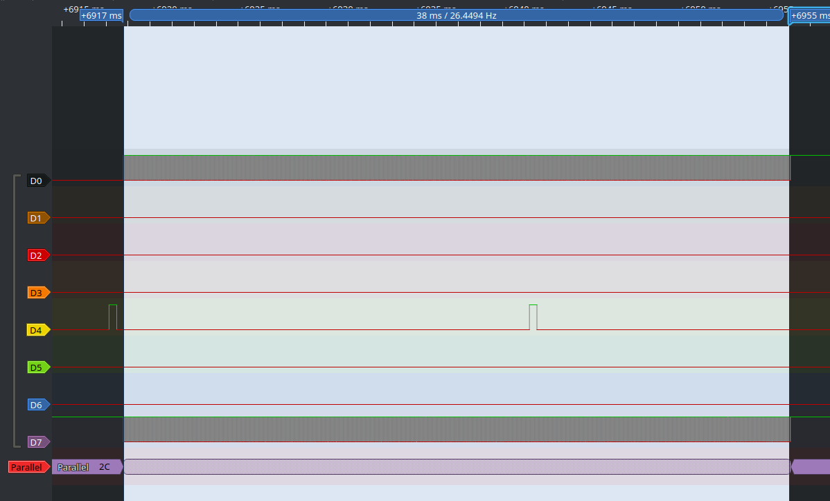
On the other hand, even if clock speed is set to its maximum, tearing effect is still noticeable. I read somewhere I2S should have no problems even with larger displays (considering I am using a 480x320 screen), so is this tearing effect expected? How could I solve it?

Code: Select all

#include "freertos/FreeRTOS.h"
#include "freertos/task.h"
#include "i2sparallel_custom.h"
#include "driver/periph_ctrl.h"
#include "driver/i2s.h"
#include "esp32/rom/lldesc.h"
#include "soc/soc.h"
#include "gfx.h"
#include "esp_log.h"
#include "gpiolcd.h"
#include "global_defs.h"

SemaphoreHandle_t xSemaphore[N_DISPLAY_BUFFERS];
_Atomic volatile bool busy;

static void i2s_setup_peripheral(void);
static void i2s_setup_clock(void);
static void i2s_isr(void *const params);

static void i2s_setup_peripheral(void)
{
    enum
    {
        I2S_TX_FIFO_MODE_16_BIT_DUAL,
        I2S_TX_FIFO_MODE_16_BIT_SINGLE,
        I2S_TX_CHAN_MODE_MONO
    };

    /* Enable I2S0 peripheral before modifying any register. */
    periph_module_enable(PERIPH_I2S0_MODULE);

    /* Set I2S0 in LCD mode. */
    I2S0.conf2.lcd_en = 1;

    /* Clear TX slave mode so LCD master
     * transmission mode is enabled. */
    I2S0.conf.tx_slave_mod = 0;

    /* Set TX channel mode. */
    I2S0.conf_chan.tx_chan_mod = I2S_TX_CHAN_MODE_MONO;

    /* Set TX FIFO mode. */
    I2S0.fifo_conf.tx_fifo_mod = I2S_TX_FIFO_MODE_16_BIT_DUAL;

    /* This bit must always be set, according to TRM. */
    I2S0.fifo_conf.tx_fifo_mod_force_en = 1;

    I2S0.conf1.tx_pcm_bypass = 1;
    I2S0.conf1.tx_stop_en = 1;
    I2S0.conf.tx_right_first = 1;
    I2S0.conf.tx_msb_right = 1;

    /* Define I2S0 transmitter channel bit length. */
    I2S0.sample_rate_conf.tx_bits_mod = 32;

    /* These bits must always be set, according to TRM
     * documentation, when working in LCD mode so LCD
     * master transmitting data frame form 2, where 1
     * byte is transmitted each time WR is asserted,
     * is used. */
    I2S0.conf2.lcd_tx_sdx2_en = 1;
    I2S0.conf2.lcd_tx_wrx2_en = 1;
}

void i2s_setup_gpio(void)
{
    {
        uint32_t signal_idx = I2S0O_DATA_OUT8_IDX;

        foreach (pin, lcd_pins)
        {
            /* Route each LCD data pin into I2S0 output signal. */
            gpio_matrix_out(*pin, signal_idx++, true, false);
        }
    }

    /* According to TRM, I2S WS signal needs to be inverted. */
    gpio_matrix_out(WR, I2S0O_WS_OUT_IDX, true, false);
}

enum
{
    OWNER_CPU,
    OWNER_DMA
};

LCDWord dma_buffers[N_DISPLAY_BUFFERS][DMA_MAX_SIZE / sizeof (LCDWord)];

static lldesc_t dma_descriptor =
{
    .size = DMA_MAX_SIZE,
    .length = DMA_MAX_SIZE,
    .buf = NULL,
    .owner = OWNER_DMA,
    .eof = 1
};

static void i2s_setup_dma(void)
{
    /* Reset DMA AHB interface. */
    I2S0.lc_conf.ahbm_rst = 1;
    I2S0.lc_conf.ahbm_rst = 0;

    /* Reset in DMA FSM. */
    I2S0.lc_conf.in_rst = 1;
    I2S0.lc_conf.in_rst = 0;

    /* Reset out DMA FSM. */
    I2S0.lc_conf.out_rst = 1;
    I2S0.lc_conf.out_rst = 0;

    /* Set owner bit. */
    I2S0.lc_conf.check_owner = 0;

    /* Transmit data in burst mode. */
    I2S0.lc_conf.out_data_burst_en = 1;

    /* Transfer outlink descriptor in burst mode. */
    I2S0.lc_conf.outdscr_burst_en = 1;

    /* Enable DMA operation over I2S0. */
    I2S0.fifo_conf.dscr_en = 1;

    /* Set up DMA descriptor address. */
    I2S0.out_link.addr = ((uint32_t)(&dma_descriptor)) & I2S_OUTLINK_ADDR;
}

static void i2s_setup_fifo(void)
{
    /* Reset DMA AHB interface FIFO buffer. */
    I2S0.lc_conf.ahbm_fifo_rst = 1;
    I2S0.lc_conf.ahbm_fifo_rst = 0;

    /* Reset I2S0 TX channel. */
    I2S0.conf.tx_reset = 1;
    I2S0.conf.tx_reset = 0;

    /* Reset I2S0 TX FIFO buffer. */
    I2S0.conf.tx_fifo_reset = 1;
    I2S0.conf.tx_fifo_reset = 0;
}

static void i2s_setup_clock(void)
{
    /* ***************************************************************
     * I2Sn clock frequency is calculated as follows:
     *
     * fi2s = fPLL / (N + (b/a))
     *
     * Where:
     *  fPLL: selected clock frequency. Two options are available:
     *          PLL_D2_CLK, rated at 160 MHz.
     *          APLL_CLK (frequency?)
     *
     *  N: CLKM_DIV_NUM
     *  b: CLKM_DIV_B
     *  a: CLKM_DIV_A
     *
     * On the other hand, BCK clock frequency is calculated as follows:
     *
     * I2SnO_BCK_out = fi2s / M
     *
     * Where:
     *
     *  M : BCK_DIV_NUM
     *
     * Note: in this case we are using LCD master transmitting mode.
     * ***************************************************************/

    /* Set BCK TX clock rate. */
    I2S0.sample_rate_conf.tx_bck_div_num = 4;
    I2S0.clkm_conf.clkm_div_b = 1;

    /* On the original example, it was set to zero. Why? */
    I2S0.clkm_conf.clkm_div_a = 0;

    /* Set clock frequency denominator. */
    I2S0.clkm_conf.clkm_div_num = 1;

    /* Activate I2S0 clock. */
    I2S0.clkm_conf.clk_en = 1;

    /* Enable interrupt trigger when a packet has been sent. */
    I2S0.int_ena.out_eof = 1;
    I2S0.int_ena.out_total_eof = 1;

    /* Enable interrupt trigger when a descriptor error is found. */
    I2S0.int_ena.out_dscr_err = 1;

#if 0
    /* Why isn't this bit enabled on the example code? */
    I2S0.int_ena.out_done = 1;
#endif
}

static void i2s_isr(void *const params)
{
    if (I2S0.int_st.out_eof || I2S0.int_st.out_total_eof)
    {
        I2S0.conf.tx_start = 0;
        I2S0.conf.tx_reset = 1;
        I2S0.conf.tx_reset = 0;

        busy = false;
    }

    /* Clear interrupt flags. */
    I2S0.int_clr.val = I2S0.int_st.val;
}

bool i2s_is_working(void)
{
    return busy;
}

static void i2s_setup_isr(void)
{
    enum
    {
        ESP_INTR_FLAGS_NONE
    };

    intr_handle_t int_handle;

    /* Configure interrupt for I2S0. */
    const esp_err_t ret = esp_intr_alloc
    (
        /* Interrupt source */  ETS_I2S0_INTR_SOURCE,
        /* Interrupt flags */   ESP_INTR_FLAGS_NONE,
        /* Interrupt handler */ i2s_isr,
        /* Parameters */        NULL,
        /* Return handle */     &int_handle
    );

    if (ret == ESP_OK)
    {
        /* This interrupt is not located in IRAM. */
        esp_intr_set_in_iram(int_handle, false);

        /* Enable interrupt. */
        esp_intr_enable(int_handle);
    }
    else
    {
        /* Could not initialize I2S0 interrupt handler. */
    }
}

void i2s_draw(const LCDWord *const buffer, const size_t elements)
{
    busy = true;

    dma_descriptor.buf = (uint8_t*)buffer;
    dma_descriptor.length = elements * sizeof (*buffer);

    if (dma_descriptor.length != DMA_MAX_SIZE)
    {
        asm volatile ("nop");
    }

    /* Enable DMA operation over I2S0. */
    I2S0.fifo_conf.dscr_en = 1;
    /* Start transmission. */
    I2S0.out_link.start = 1;
    I2S0.conf.tx_start = 1;
}

void i2s_setup(void)
{
    /* Setup I2S0 peripheral and its registers. */
    i2s_setup_peripheral();

    /* Setup GPIO pins used by I2S0. */
    i2s_setup_gpio();

    /* Setup DMA channel for I2S0. */
    i2s_setup_dma();

    /* Setup I2S0 clock. */
    i2s_setup_clock();

    /* Reset I2S0 FIFO buffers. */
    i2s_setup_fifo();

    /* Setup interrupt handler. */
    i2s_setup_isr();

    _Static_assert((DMA_MAX_SIZE % sizeof (uint32_t)) == 0, "DMA buffer size is not word-aligned");

    _Static_assert(DMA_MAX_SIZE <= 4092, "Exceeded maximum allowed DMA buffer size");
}
P.S.: as for the foreach macro, this is how it is implemented:

Code: Select all

#define lengthof(A)                     \
    _Generic(&(A),                      \
    typeof((A)[0]) *const *: (void)0,   \
    typeof((A)[0]) **: (void)0,         \
    default: sizeof(A) / sizeof((A)[0]))

/** This macro simulates a "foreach" instruction (as found in many
 * other high-level languages) which loops inside an array of any type.
 * Array element mutability is given by the array type itself.
 *
 * Note: this version requires a C99-compliant compiler and the GCC
 * extension "typeof". Compiler flag "-std=gnu99" must be explicitely given. */
#define foreach(element, array)                                                 \
    for (                                                                       \
            /* Loop initialization. */                                          \
                                                                                \
            /* C99 allows defining variables inside a "for" loop,
             * but no more than one type can be used at the same time.
             * However, this can be easily solved by the use a struct
             * which does contain the elements and types we need. */            \
            struct                                                              \
            {                                                                   \
                /* Pointer to an element in the array.
                 * By the use of the "typedef" operator,
                 * pointer type is automatically assigned
                 * by the compiler. */                                          \
                typeof (*array) *p;                                             \
                                                                                \
                /* As this "foreach" implementation relies on a nested
                 * "for" loop (which is needed to initialize an integer
                 * variable out of the pointer above), we need an auxiliary
                 * variable in order to detect whether the user has inserted
                 * a "break" instruction inside the inner loop.
                 *
                 * If no "break" is entered by the user, this variable
                 * shall oscillate between 0 and 1 depending on which
                 * loop is being exited.
                 *
                 * Otherwise, this variable will equal zero if the inner
                 * loop is suddenly exited. This causes the outer loop
                 * to be exited as well, as it is required that brk == 0. */    \
                char brk;                                                       \
            } __a =                                                             \
            {                                                                   \
                .p = array,                                                     \
                .brk = 0                                                        \
            };                                                                  \
                                                                                \
            /* Loop condition. */                                               \
                                                                                \
            /* As explained above, the pointer is used at the same time
             * as an iterator by using pointer arithmetic, as substracting
             * the address held by the pointer by the address of the array
             * first element simply returns the number of elements.
             * On the other hand, "brk" must be checked against zero, so
             * it can be detected whether the user has used a "break"
             * instruction. */                                                  \
            (__a.p - array) < lengthof(array) && !__a.brk;                    \
                                                                                \
            /* Instructions after each iteration. */                            \
                                                                                \
            /* When increasing the pointer, the next element from the
             * array is pointed. On the other hand, the auxiliary variable
             * is decreased so, if no "break" instruction is used by the
             * user, it goes back from 1 to 0. */                               \
            __a.p++, __a.brk--                                                  \
        )                                                                       \
        /* This loop is never executed more than once, but it is needed
         * to define the target variable the user wants. "__a.brk" is
         * incremented for two reasons: to detect a "break" instruction
         * entered by the user and to avoid this loop from being
         * executed more than once.
         * "__a" is hidden to the user and "element" can be used, instead.
         * Mutability depends on the array type itself, so "element" cannot
         * be modified when using "foreach" on an array of "const" elements. */ \
        for (const typeof (*array) *const element = __a.p; !__a.brk; __a.brk++)
Thanks for your help.

Xavi

ESP_Sprite
Posts: 9020
Joined: Thu Nov 26, 2015 4:08 am

Re: How to use I2S along with 8-bit parallel bus

Postby ESP_Sprite » Fri May 24, 2019 3:53 am

I don't see anything particularily sketchy in your code, but you are aware that the I2S peripheral shifts out the bytes in a weird way? If I recall correctly, a word like 0x12345678 would be sent as 0x34, 0x12, 0x78, 0x56. You probably need to shift your DMA data in a similar way.

Wrt tearing, that's mostly an artifact that happens when the location of the written data and the location of the current scanline interfere with eachother. You'd have to sync the two up (using e.g. a TE output on your display) to even start about getting rid of it. It's even worse when you write data in the direction perpendicular to the scan direction of the display, you're more-or-less guaranteed big diagonal tears that way.

Xavi92
Posts: 45
Joined: Thu Mar 28, 2019 2:26 pm

Re: How to use I2S along with 8-bit parallel bus

Postby Xavi92 » Thu May 30, 2019 5:15 pm

Hi Sprite,

Sorry for the delayed answer. I did some more tests and got to send buffer as expected, as shown at the image below (I am filling a buffer with 0xFFFF and 0x0000):

Image

However, if I control I2S1.conf.tx_start manually (setting it before sending a buffer and resetting it once sent under ISR), there are extra clocks that are still being asserted before the ISR gets executed, causing wrong colors on the screen after the first transfer.

(When I2S1.conf.tx_start is manually controlled)
Image

The extra clocks issue seems to be solved by setting I2S1.conf1.tx_stop_en on startup so WS gets stopped as soon as TX FIFO buffer is empty.

(When I2S1.conf.tx_start is only set when buffer needs to be sent and reset automatically by I2S1.conf1.tx_stop_en)
Image

However, even if I set I2S1.conf.tx_start for the second time after the first transfer, I2S1 does not work anymore and no more transfers are made other than the first one.

(The huge ~1 second delay between LCD initialization and the first I2S+DMA transfer is on purpose for debugging purposes)

Image

However, when I2S1.conf1.tx_stop_en is disabled and I2S1.conf.tx_start is controlled manually, several transfers are possible:

Image

So my question is: why several transfers are not working on I2S1.conf1.tx_stop_en == 1 and what should I do to get them?

This is the source code I am currently using:

Code: Select all

#include "freertos/FreeRTOS.h"
#include "freertos/task.h"
#include "i2sparallel_custom.h"
#include "driver/periph_ctrl.h"
#include "driver/i2s.h"
#include "esp32/rom/lldesc.h"
#include "soc/soc.h"
#include "gfx.h"
#include "esp_log.h"
#include "gpiolcd.h"
#include "global_defs.h"

static void i2s_setup_peripheral(void);
static void i2s_setup_clock(void);
static void i2s_isr(void *const params);

static void i2s_setup_clock(void)
{
    /* ***************************************************************
     * I2Sn clock frequency is calculated as follows:
     *
     * fi2s = fPLL / (N + (b/a))
     *
     * Where:
     *  fPLL: selected clock frequency. Two options are available:
     *          PLL_D2_CLK, rated at 160 MHz.
     *          APLL_CLK (frequency?)
     *
     *  N: CLKM_DIV_NUM
     *  b: CLKM_DIV_B
     *  a: CLKM_DIV_A
     *
     * On the other hand, BCK clock frequency is calculated as follows:
     *
     * I2SnO_BCK_out = fi2s / M
     *
     * Where:
     *
     *  M : BCK_DIV_NUM
     *
     * Note: in this case we are using LCD master transmitting mode.
     * ***************************************************************/

    /* Set BCK TX clock rate. */
    I2S1.sample_rate_conf.tx_bck_div_num = 2;
    I2S1.clkm_conf.clkm_div_b = 0;

    /* On the original example, it was set to zero. Why? */
    I2S1.clkm_conf.clkm_div_a = 1;

    /* Set clock frequency denominator. */
    I2S1.clkm_conf.clkm_div_num = 8;

    /* Activate I2S1 clock. */
    I2S1.clkm_conf.clk_en = 1;

    /* Enable interrupt trigger when a packet has been sent. */
    I2S1.int_ena.out_eof = 1;
    I2S1.int_ena.out_total_eof = 1;

    /* Enable interrupt trigger when a descriptor error is found. */
    I2S1.int_ena.out_dscr_err = 1;

#if 0
    /* Why isn't this bit enabled on the example code? */
    I2S1.int_ena.out_done = 1;
#endif
}

static void i2s_setup_peripheral(void)
{
    enum
    {
        I2S_TX_CHAN_MODE_MONO = 2,
        I2S_TX_FIFO_MODE_16_BIT_DUAL = 0,
        I2S_TX_FIFO_MODE_16_BIT_SINGLE = 1
    };

    /* Enable I2S1 peripheral before modifying any register. */
    periph_module_enable(PERIPH_I2S1_MODULE);

    /* Set I2S1 in LCD mode. */
    I2S1.conf2.lcd_en = 1;

    /* Clear TX slave mode so LCD master
     * transmission mode is enabled. */
    I2S1.conf.tx_slave_mod = 0;

    I2S1.conf1.tx_stop_en = 1;
    I2S1.conf1.tx_pcm_bypass = 1;

    /* Set TX channel mode. */
    I2S1.conf_chan.tx_chan_mod = I2S_TX_CHAN_MODE_MONO;

    /* Reset I2S1 TX FIFO buffer. */
    I2S1.conf.tx_fifo_reset = 1;
    I2S1.conf.tx_fifo_reset = 0;

    /* Set TX FIFO mode. */
    I2S1.fifo_conf.tx_fifo_mod = I2S_TX_FIFO_MODE_16_BIT_SINGLE;

    /* This bit must always be set, according to TRM. */
    I2S1.fifo_conf.tx_fifo_mod_force_en = 1;

    /* These bits must always be set, according to TRM
     * documentation, when working in LCD mode so LCD
     * master transmitting data frame form 2, where 1
     * byte is transmitted each time WR is asserted,
     * is used. */
    I2S1.conf2.lcd_tx_sdx2_en = 0;
    I2S1.conf2.lcd_tx_wrx2_en = 1;
}

static const enum LCDPins lcd_pins[] =
{
    DB0,
    DB1,
    DB2,
    DB3,
    DB4,
    DB5,
    DB6,
    DB7
};

void i2s_setup_gpio(void)
{
    {
        uint32_t signal_idx = I2S1O_DATA_OUT0_IDX;

        foreach (pin, lcd_pins)
        {
            /* Route each LCD data pin into I2S1 output signal. */
            gpio_matrix_out(*pin, signal_idx++, false, false);
        }
    }

    /* According to TRM, I2S WS signal needs to be inverted. */
    gpio_matrix_out(WR, I2S1O_WS_OUT_IDX, true, false);
}

void i2s_reset_gpio(void)
{
    foreach (pin, lcd_pins)
    {
        /* Unroute each LCD data pin into I2S1 output signal. */
        gpio_matrix_out(*pin, 0x100, false, false);
    }

    /* According to TRM, I2S WS signal needs to be inverted. */
    gpio_matrix_out(WR, 0x100, false, false);
}

enum
{
    OWNER_CPU,
    OWNER_DMA
};

LCDType dma_buffers[2][DMA_MAX_SIZE / 2];

static lldesc_t dma_descriptor =
{
    .size = DMA_MAX_SIZE,
    .length = DMA_MAX_SIZE,
    .buf = NULL,
    .owner = OWNER_DMA,
    .eof = 1
};

static void i2s_setup_dma(void)
{
    /* Reset DMA AHB interface. */
    I2S1.lc_conf.ahbm_rst = 1;
    I2S1.lc_conf.ahbm_rst = 0;

    /* Reset in DMA FSM. */
    I2S1.lc_conf.in_rst = 1;
    I2S1.lc_conf.in_rst = 0;

    /* Reset out DMA FSM. */
    I2S1.lc_conf.out_rst = 1;
    I2S1.lc_conf.out_rst = 0;

    /* Set owner bit. */
    I2S1.lc_conf.check_owner = 1;

    /* Transmit data in burst mode. */
    I2S1.lc_conf.out_data_burst_en = 1;

    /* Transfer outlink descriptor in burst mode. */
    I2S1.lc_conf.outdscr_burst_en = 1;

    /* Enable DMA operation over I2S1. */
    I2S1.fifo_conf.dscr_en = 1;

    /* Set up DMA descriptor address. */
    I2S1.out_link.addr = ((uint32_t)(&dma_descriptor)) & I2S_OUTLINK_ADDR;
}

static void i2s_setup_fifo(void)
{
    /* Reset DMA AHB interface FIFO buffer. */
    I2S1.lc_conf.ahbm_fifo_rst = 1;
    I2S1.lc_conf.ahbm_fifo_rst = 0;

    /* Reset I2S1 TX FIFO buffer. */
    I2S1.conf.tx_fifo_reset = 1;
    I2S1.conf.tx_fifo_reset = 0;

    /* Reset I2S1 TX channel. */
    I2S1.conf.tx_reset = 1;
    I2S1.conf.tx_reset = 0;
}

static void IRAM_ATTR i2s_isr(void *const params)
{
    static uint8_t buffer_selector;
    /* Retrieve semaphore handle for currently selected DMA buffer. */
    const SemaphoreHandle_t semaphore = xSemaphore[buffer_selector];

    BaseType_t xHigherPriorityTaskWoken = pdFALSE;

    if (I2S1.int_st.out_eof || I2S1.int_st.out_done || I2S1.int_st.out_total_eof)
    {
        buffer_selector ^= 1;
    }

    /* Clear interrupt flags. */
    I2S1.int_clr.val = I2S1.int_st.val;

    /* Inform gfx transmission has ended. */
    xQueueSendToBackFromISR(draw_isr_queue, UNUSED(bool), &xHigherPriorityTaskWoken);

    xSemaphoreGiveFromISR(semaphore, &xHigherPriorityTaskWoken);

    if (xHigherPriorityTaskWoken)
    {
        portYIELD_FROM_ISR();
    }
}

static void i2s_setup_isr(void)
{
    enum
    {
        ESP_INTR_FLAGS_NONE
    };

    intr_handle_t int_handle;

    /* Configure interrupt for I2S1. */
    const esp_err_t ret = esp_intr_alloc
    (
        /* Interrupt source */  ETS_I2S1_INTR_SOURCE,
        /* Interrupt flags */   ESP_INTR_FLAGS_NONE,
        /* Interrupt handler */ i2s_isr,
        /* Parameters */        NULL,
        /* Return handle */     &int_handle
    );

    if (ret == ESP_OK)
    {
        /* This interrupt is not located in IRAM. */
        esp_intr_set_in_iram(int_handle, true);

        /* Enable interrupt. */
        esp_intr_enable(int_handle);
    }
    else
    {
        /* Could not initialize I2S1 interrupt handler. */
    }
}

void i2s_draw(const LCDType *const buffer)
{
    dma_descriptor.buf = (uint8_t*)buffer;

    i2s_setup_dma();
    i2s_setup_fifo();

    /* Start transmission. */
    I2S1.out_link.start = 1;
    I2S1.conf.tx_start = 1;
}

void i2s_setup(void)
{
    /* Setup I2S1 peripheral and its registers. */
    i2s_setup_peripheral();

    /* Setup GPIO pins used by I2S1. */
    i2s_setup_gpio();

    /* Setup DMA channel for I2S1. */
    i2s_setup_dma();

    /* Setup I2S1 clock. */
    i2s_setup_clock();

    /* Reset I2S1 FIFO buffers. */
    i2s_setup_fifo();

    /* Setup interrupt handler. */
    i2s_setup_isr();
}

Xavi92
Posts: 45
Joined: Thu Mar 28, 2019 2:26 pm

Re: How to use I2S along with 8-bit parallel bus

Postby Xavi92 » Tue Jun 04, 2019 7:10 pm

ESP_Sprite wrote:
Fri May 24, 2019 3:53 am
I don't see anything particularly sketchy in your code, but you are aware that the I2S peripheral shifts out the bytes in a weird way? If I recall correctly, a word like 0x12345678 would be sent as 0x34, 0x12, 0x78, 0x56. You probably need to shift your DMA data in a similar way.
I can confirm such behaviour. I am filling a 4092-byte buffer as {0x0000, 0x0001, 0x0002...} and, as you can see at the image below, it is being sent in reverse. This is not a critical issue, though.
Image
ESP_Sprite wrote:
Fri May 24, 2019 3:53 am
Wrt tearing, that's mostly an artifact that happens when the location of the written data and the location of the current scanline interfere with eachother. You'd have to sync the two up (using e.g. a TE output on your display) to even start about getting rid of it. It's even worse when you write data in the direction perpendicular to the scan direction of the display, you're more-or-less guaranteed big diagonal tears that way.
I have reduced TFT driver frame rate to 42 Hz so the artifacts are now less visible. However, I2S1 seems to write at ~26fps, so the artifacts are still there. WR clock is rated at ~8 Mhz - is there any possibility to make I2S1 faster?

Xavi92
Posts: 45
Joined: Thu Mar 28, 2019 2:26 pm

Re: How to use I2S along with 8-bit parallel bus

Postby Xavi92 » Mon Jun 10, 2019 4:21 pm

As shown below, a complete screen takes ~38 ms, but the tearing effect signal (see D4) asserts every 24 ms. 480 x 320 x 2bpp = 307200 bytes are being sent there, so this approaches to ~8 Mbytes per second. However, is there any way to make I2S1 transfer shorter than 24 ms?

Image

I2S1 is being configured as follows:

Code: Select all

    rtc_clk_apll_enable(true, ULONG_MAX, ULONG_MAX, 8, 0);

    /* Set BCK TX clock rate. */
    I2S1.sample_rate_conf.tx_bck_div_num = 4;
    I2S1.clkm_conf.clkm_div_b = 1;

    /* On the original example, it was set to zero. Why? */
    I2S1.clkm_conf.clkm_div_a = 0;

    /* Set clock frequency denominator. */
    I2S1.clkm_conf.clkm_div_num = 1;

    /* Enable use of APLL. */
    I2S1.clkm_conf.clka_en = 1;
Thanks for your help. :)

Baldhead
Posts: 434
Joined: Sun Mar 31, 2019 5:16 am

Re: How to use I2S along with 8-bit parallel bus

Postby Baldhead » Wed Nov 20, 2019 7:54 pm

Hi Xavi92,

I'm trying to do the same thing you did(new driver with static allocation memory), but the espressif documentation is very bad.

My problem i think that are here:
"viewtopic.php?f=13&t=12905"

In "esp32_technical_reference_manual_en.pdf", page 119, says:
However, unlike the SPI DMA channels, the data size for a single transfer is one word, or four bytes.

* My data buffer are of type uint16_t.
* The i2s lcd mode are 8 bits parallel.
* The dma data size for a single transfer is one word, or four bytes( uint32_t ).
* The data read/write packet length for a FIFO operation is 32 bits.
* The dma descriptor are in byte size.

If i want to write only one byte or a number of bytes that are not multiple of 4 bytes ?


I think that i need configure these register in a correct way:
* I2S_TX_FIFO_MOD[2:0]
* I2S_TX_CHAN_MOD[2:0]
* I2S_TX_MSB_RIGHT
* I2S_TX_BITS_MOD
* I2S_TX_RIGHT_FIRST
* I2S_TX_MSB_SHIFT

Can you post your full i2s driver here ?

Thank's.

Ranger
Posts: 1
Joined: Thu Jul 23, 2020 2:13 am

Re: How to use I2S along with 8-bit parallel bus

Postby Ranger » Thu Jul 23, 2020 3:56 am

Hi, gentlemans.
Is any progress to drive TFT module via 8bit bus using I2S ?

Who is online

Users browsing this forum: No registered users and 63 guests