Page 3 of 3
Re: Antenna design
Posted: Wed Jul 26, 2023 8:22 pm
by svenbieg
I've had time and played around a bit. I changed nothing, i just increased the cupper-cells to 256. This calculation took about 3 times longer. Your design now looks like an illusion to me:
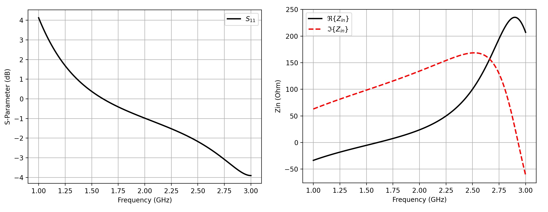
Your antenna doesn't have a resonance-frequency anymore.
I have an even higher directivity and almost hit the 2.4GHz:
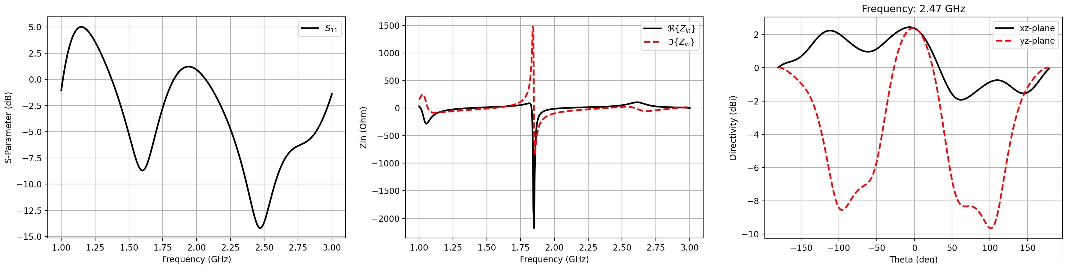
You can find the STLs and the Python-scripts in the attachment.
Re: Antenna design
Posted: Thu Jul 27, 2023 2:19 am
by Sprite
Hm, seems like the simulation is incredible sensitive to simulation parameters; you're right in that a higher cell density makes the resonance disappear but increasing the number of timestamps (NrTS) to e.g. 180000 makes it re-appear, even though the S-numbers are a lot lower than before. I'm decently sure this is a simulation artefact, given the fact that mPIFA antennas like the ones we use are
known to have S11-numbers down to -24dB. To be honest, I also don't know how to pick the parameters in such a way that we can be sure they reflect reality.
Re: Antenna design
Posted: Thu Jul 27, 2023 12:22 pm
by svenbieg
I give up at this point. The people at Texas Instruments already have proofed their calculation in reality, i'm not able to do so.
Maybe i'll post a photo of my smartphone when it is broken, and if i can find the WiFi-antenna.
Re: Antenna design
Posted: Sun Jul 30, 2023 9:18 am
by Sprite
Yeah, it's a shame, I hoped I found some way to 'prove' antennas to be good or bad, but it seems OpenEMS is so finnicky that at least I cannot really use it for it.
Re: Antenna design
Posted: Mon Jul 31, 2023 1:44 am
by svenbieg
The calculation is really simple with my graphical solution:
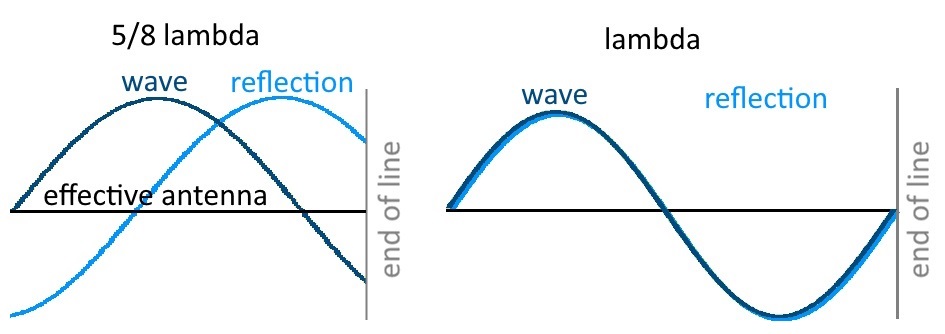
When transmitting we push electrons into the antenna. These electrons are pushing the neighbours, a wave moves through the antenna at the speed of light. This wave gets reflected at the end of the antenna, because electrons can't be pushed out of the line. The electrons bounce off and the wave gets back to the transceiver. In reality it is a series of waves, the waves and the reflections are overlaying. This may be difficult to imagine first, but You can easily solve this graphically by drawing a sinus-curve. If the curve is going up at 0.5, it is going down at -0.5 in the opposite direction at the end of the line.
Let's say our transmitting antenna is vertical (Y), the electrons are swinging up and down. It is right in front of Your monitor (Z) and far away, so another spherical wave from the middle of our effective antenna hits the monitor in a flat way. The Lorentz-force causes all electrons in the receiving antenna to be diverted left or right (X) at the same time.

The electrons can't move against each other in our meandered antenna, we have to sum up all forces. I simply connect the ends of the line and get my effective antenna. If we turn it a bit we get the best result.
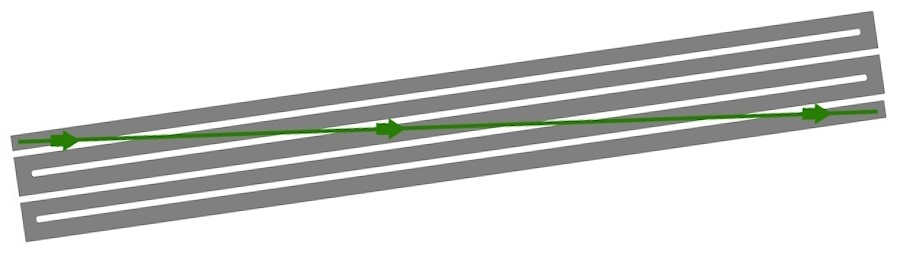
The electrons are moving forward and backward in the receiving antenna with the same frequency like those in the transmitting antenna, that's what we want.
This is not a theory, this is know-how. My formula let's You predict the measurement-result with an oscilloscope, and even OpenEMS.
Re: Antenna design
Posted: Wed Aug 02, 2023 3:24 am
by Sprite
Sorry, but any theoretical explanation isn't gonna cut it against the razor of 'if it really was that simple, everyone would have figured this out already and we'd see this everywhere'. A working meandered unipole would have a lot of advantages: its frequency is only dependent on the length and presumably there's very few effects from the underlying material (FR4, housing of the device etc) that can de-tune it. If it is that advantageous and we're both amateurs in this field, this design should be immediately obvious to anyone in the field and you see it everywhere. The fact that we don't immediately tells me that there's something to the design that you're overlooking with your theoretical explanation that makes it unsuitable.
Re: Antenna design
Posted: Wed Aug 02, 2023 4:40 am
by svenbieg
How can You be sure, without giving it a try?
My design has a 100% better result in OpenEMS.
Me 'amateur' could easily turn my home into a laboratory to figure out the performance.
To me it looks like the 'inverted F antenna'-people have found it out without my formula.
Re: Antenna design
Posted: Wed Aug 02, 2023 1:12 pm
by Sprite
How can You be sure, without giving it a try?
I cannot be, that's why I called the method a 'razor' and not 'proof'. It tells me that unless there's a very good explanation (and that does not include any theoretical-only one), it's probably not worth spending time on.
(To put a name on it: this would probably fall under Sagans standard: 'Extraordinary claims require extraordinary evidence.' The extraordinary claim here is your implicit assumption that you are the first to discover a superior antenna design so simple that loads of other people could have thought of it before, but no one actually has.)
My design has a 100% better result in OpenEMS.
The last results you posted? If those results are correct, your antenna only had a S11 of -12dB, which as an antenna is a pretty shit rating. Given the fact that the mPIFA is known to perform better than the results you got, I think the more likely explanation is that the simulation gave bogus results for some reason.
Re: Antenna design
Posted: Wed Aug 02, 2023 2:31 pm
by svenbieg
Yes, i mean my last post. In the document of Texas Instruments You have posted, they say their goal was to reach -10dB, so 90% of the energy would be delivered to the antenna.
What makes my result interesting is the resonance in the far field, the signal-strength is 100% higher. This is where the communication happens, here are Your missing 4dB.
Re: Antenna design
Posted: Sat Aug 05, 2023 8:06 pm
by svenbieg
I found this in my Bluetooth-headset today, the antenna has about 2 lambda.
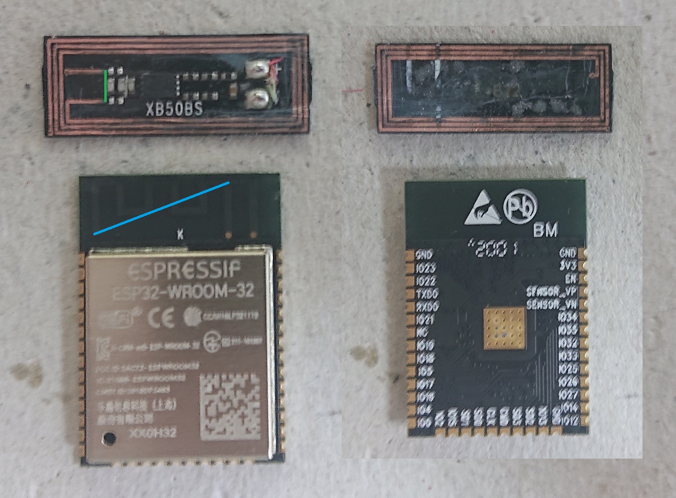
The effective antenna seems to be very short, it is the missing line between the feet on the left. Maybe this is by design because it was a headset.
Looks like two antennas that are connected at the end. I never thought of this, but this could work. With an open one You can put the end away of the transceiver, what makes it more efficient.
It was a Sony.
