Page 1 of 1
Data Resistor Value
Posted: Fri Aug 15, 2025 3:22 pm
by Jblight32
I am confused how to calculate the proper resistor needed for the data lines on two, 1-meter long WS2813 LED strips.
From the ESP32U I am connecting pins 17 & 19 to a SN74AHCT125N booster exactly as in the diagram.
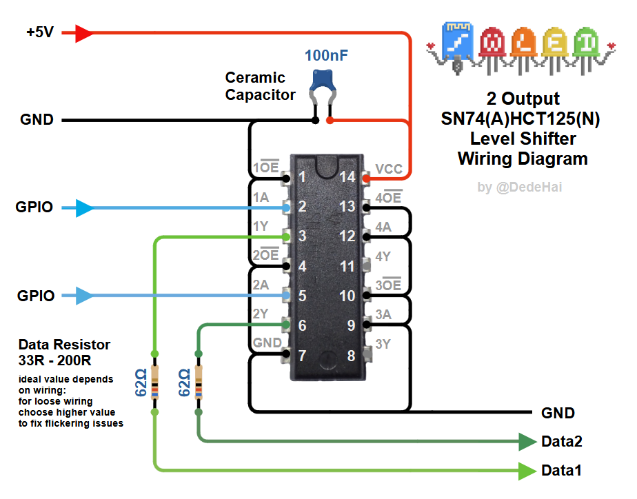
- Shifter74HCT125_Dual.png (160.57 KiB) Viewed 644 times
What I cant find clarification on is how it says "Data Resistor 33-200, ideal value depends on wiring..."
Data line #1 is 24" long, 16ga wire
Data Line #2 is 48" long, 16ga wire
How should I go about finding the optimal resistor value and wattage for each data line?
Should I put the resistor right before the LED strip, or right after the SN74AHCT125N?
Re: Data Resistor Value
Posted: Fri Aug 15, 2025 6:09 pm
by MicroController
How should I go about finding the optimal resistor value and wattage for each data line?
Probably best to ask the person who says you need the magic resistors in those places.
It should work without any resistors, but equally well with any resistor value from the given range.
Wattage is irrelevant as there's basically zero current going through the resistors, so probably not even micro-watts of power to dissipate.
Re: Data Resistor Value
Posted: Sun Aug 17, 2025 11:08 am
by Jblight32
Well the wiring diagram is very specific, figured there was a reason.
After going through the datasheets...
The WS2813 (I think version A), shows : RGB Channel Constant Current = 16mA
The SN74AHCT125N Shows : Output clamp current = 20mA
Continuous output current = 25mA
Absolute maximum ratings
They are close... you don't think the output signal of the SN74AHCT125N is more than the WS2813 can take without a resistor?
Re: Data Resistor Value
Posted: Sun Aug 17, 2025 7:32 pm
by MicroController
Nope.
The 18mA constant current is the drive current of the three individual LED chips inside the WS2813 and it's sourced from the power supply (VDD pin). The data input pins are high-impedance and there's almost no current into/out of them ("+/- 1uA max").
Re: Data Resistor Value
Posted: Mon Aug 18, 2025 4:13 am
by Jblight32
Thanks! I'll give it a shot
Last time I had a problem with one of the two WS2812b LED strips, it would have a very brief flicker of crazy colors every few seconds... the problem still persisted even after I replaced both the ESP controller and LED strip.
The WS2812b was connected to the ESP32 output pin with a 100Ω resistor instead of going through the SN74AHCT125N I'm now using. Wire distance was only 6 inches.
That's why I'm using the SN74A and WS2813 LED strips now... to fix that problem
Re: Data Resistor Value
Posted: Mon Aug 18, 2025 7:33 am
by MicroController
Yes, level-shifting the signal to 5V can definitely improve the reliability of the signals.
Even more important is the accurate sub-microsecond timing of the pulses. That's something you can only achieve reliably in hardware on an ESP32, e.g. by using the RMT peripheral.
Re: Data Resistor Value
Posted: Mon Aug 18, 2025 1:56 pm
by Jblight32
Im using the WLED software
Re: Data Resistor Value
Posted: Wed Aug 20, 2025 11:44 am
by Jblight32
Had some trouble with the ESP32U devkit boards I got on ebay.
It has a micro-usb adapter but after connecting it, no com port shows up in windows.
I tried using the boot button and also tying IO0 to gnd, still nothing.
Any idea why this is? I tried multiple cables, esp32u boards and different usb ports.
Eventually I used an FTDI adapter and grounded pin IO0, this allowed me to finally program them.
Ran a quick test on the WS2813 led's using the SN74 without a resistor on the data line... seems to work fine!
Re: Data Resistor Value
Posted: Wed Aug 20, 2025 9:51 pm
by MicroController
Might be that you don't have the right driver installed on the PC for the USB<->UART chip on those boards.