When I started with ESP32, it took me a while to figure out the product matrix had an axis of IC (SOC, system on a chip), Module, Dev board, in addition to the axis of <no suffix>, S<n>, C<n>, H, 8266. (And another axis about the WIFI antenna.) Mostly I get 3rd party development boards on Amazon, but I did get some modules and hand soldered them to a PCB.
Dev Board
These are 10 pins per inch. Hand soldering is easy. Check the schematic for your board; most likely it expects 5V on the VDD_5V pin. All the Amazon vendors seem to make small changes to the dev boards: pins, leds, size, camera, usb. You might not find a perfect schematic for any particular board; a magnifying glass is helpful.
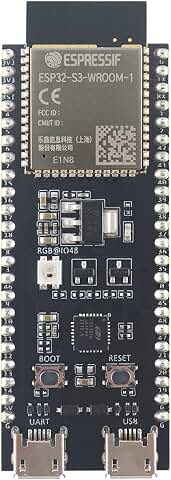
- DevelopmentBoard.jpg (17.47 KiB) Viewed 36 times
The dev board has a module soldered to it, at the top in the picture above.
Module
These are 20 pins per inch, hand soldering is possible. Check the module doc; most likely it wants 3.3V. The module has a printed antenna or a connector (printed in these pictures).
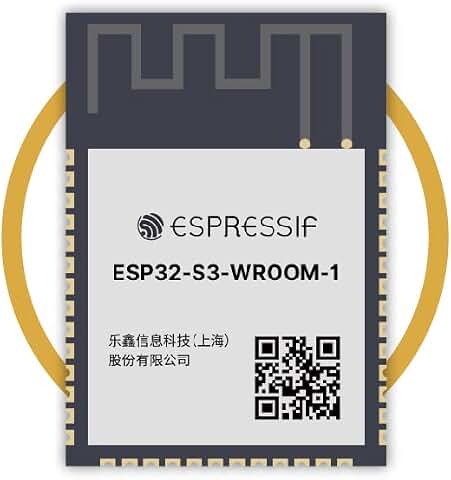
- Module.jpg (17.77 KiB) Viewed 36 times
If you pry off the metal cover on the module, there are tiny ICs inside, and maybe some external memory.
IC (CPU)
The IC is 7mm -- tiny. Beyond my skill level.
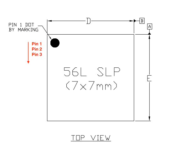
- IC.png (12.01 KiB) Viewed 36 times
Inside the CPU it is turtles, all the way down.