Does anyone know how to use SPI with ESP-32 cam? I'm currently integrating an RFID reader with the esp-32 cam.
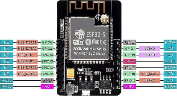
I have a PIN diagram here:
https://www.seeedstudio.site/media/cata ... 32cam3.jpg)
but it doesn't have the data for the SPI pins like the one I have for my other devboard here:
https://www.shenzhen2u.com/NodeMCU-32S
I did find a table for the SPI pins from the Espressif docs, but since the VSPI pins aren't in the esp32-cam, I ended up using HSPI, but it doesn't seem to work.
https://docs.espressif.com/projects/esp ... aster.html
I found a schematic diagram, but unfortunately I can't read schematics since I come from a software engineering background:
https://github.com/SeeedDocument/forum_ ... M_V1.6.pdf
However, I did try to read it to the best of my ability, and I think the top right part (P1, P2) correspond to the header pins of the devboard. Incidentally, none of them are SDA, etc. (like shown in the esp32 module standalone of the left).
Does that mean I can't use it if the header pins don't have it and it's being used by the sdcard? The blurb for the devboard says it supports SPI, but I'm not sure how to use the SPI lines if it's not exposed as a header pin.
Using SPI with AI thinker ESP-32-cam
Re: Using SPI with AI thinker ESP-32-cam
Did you ever happen to find a solution to your problem:
Thanks!
??Using SPI with AI thinker ESP-32-cam
Thanks!
Re: Using SPI with AI thinker ESP-32-cam
It's works for me:
It's all about forced initialization of the SPI bus with the given pins:
--
I hope it helps someone
Code: Select all
#include <SPI.h>
#include <MFRC522.h>


#define MISO_PIN        12
#define MOSI_PIN        13
#define SCK_PIN         14
#define SS_PIN          15
#define RST_PIN         16


MFRC522 mfrc522(SS_PIN, RST_PIN);  // Create MFRC522 instance

void setup() {
	delay(2000);
	Serial.begin(115200);		// Initialize serial communications with the PC
	while (!Serial);		// Do nothing if no serial port is opened (added for Arduinos based on ATMEGA32U4)

	// void SPIClass::begin(sck, miso, mosi, ss)
	SPI.begin(SCK_PIN, MISO_PIN, MOSI_PIN, SS_PIN);			// Init SPI bus
	mfrc522.PCD_Init();		// Init MFRC522
	delay(40);				// Optional delay. Some board do need more time after init to be ready, see Readme
	mfrc522.PCD_DumpVersionToSerial();	// Show details of PCD - MFRC522 Card Reader details
	Serial.println(F("Scan PICC to see UID, SAK, type, and data blocks..."));
}

void loop() {
	// Reset the loop if no new card present on the sensor/reader. This saves the entire process when idle.
	if ( ! mfrc522.PICC_IsNewCardPresent()) {
		return;
	}

	// Select one of the cards
	if ( ! mfrc522.PICC_ReadCardSerial()) {
		return;
	}

	// Dump debug info about the card; PICC_HaltA() is automatically called
	mfrc522.PICC_DumpToSerial(&(mfrc522.uid));
}
Code: Select all
// void SPIClass::begin(sck, miso, mosi, ss)
SPI.begin(SCK_PIN, MISO_PIN, MOSI_PIN, SS_PIN);			// Init SPI bus
I hope it helps someone
Re: Using SPI with AI thinker ESP-32-cam
I am using ESP32-CAM Module with `DFRobot CAN Shield` , communicates with the SPI bus.
I am using Ardiono IDE v2.3.6 , and choos to using `AI Thinker ESP32-CAM` module .
I'd change the begin() function of DFRobot (in file`DFRobot_MCP2515.cpp`) :
Original:
==>
And, I don't know why, if I use GPIO 16, it automatically reboots.
So I changed it to GOIO 2 :
After I turn on the debug information , I found that :
Although It init SPI successful :
`12:07:40.972 -> [ 936][ I][SPI.cpp:113] begin(): YG.SPI: _spi_num=3(VSPI), sck=14, so=12, si=13, ss=15`
but SPI will be closed by something ?
`12:07:41.008 -> [ 979][ D][esp32-hal-spi.c:221] spiDetachBus(): Stopping SPI bus[3]/4: sck=-1, so=12, si=-1, ss=-1, clock=10227713.`
, reported by function `static bool spiDetachBus(void *bus)`
in file `c:/Users/<User>/AppData/Local/Arduino15/packages/esp32/hardware/esp32/3.3.0-alpha1/cores/esp32/esp32-hal-spi.c`
I don't know why !??
Log on boot :
Is there any comments, thanks a lot.
I am using Ardiono IDE v2.3.6 , and choos to using `AI Thinker ESP32-CAM` module .
I'd change the begin() function of DFRobot (in file`DFRobot_MCP2515.cpp`) :
Original:
Code: Select all
uint8_t DFRobot_MCP2515::begin(uint8_t speedset) {
    pinMode(_csPin, OUTPUT);
    digitalWrite(_csPin, HIGH);

    SPI.begin();	 // !!!!

    mcpReset();

    uint8_t res;
    res = mcpInit(speedset);
    if (res == MCP2515_OK) return CAN_OK;
    else return CAN_FAILINIT;
}
Code: Select all
uint8_t DFRobot_MCP2515::begin(uint8_t speedset, uint8_t SCK_PIN, uint8_t MISO_PIN, uint8_t MOSI_PIN, uint8_t SS_PIN) {
    pinMode(_csPin, OUTPUT);
    digitalWrite(_csPin, HIGH);

        SPI.begin(SCK_PIN, MISO_PIN, MOSI_PIN, SS_PIN);                 // Init SPI bus !!!!
    mcpReset();

    uint8_t res;
    res = mcpInit(speedset);
    if (res == MCP2515_OK) return CAN_OK;
    else return CAN_FAILINIT;
}
And, I don't know why, if I use GPIO 16, it automatically reboots.
So I changed it to GOIO 2 :
Code: Select all
#define SPI_RST_PIN 2    // 16:=CRASH  !??
#define SPI_SCK_PIN 14
#define SPI_SS_PIN 15
#define SPI_MOSI_PIN 13
#define SPI_MISO_PIN 12
After I turn on the debug information , I found that :
Although It init SPI successful :
`12:07:40.972 -> [ 936][ I][SPI.cpp:113] begin(): YG.SPI: _spi_num=3(VSPI), sck=14, so=12, si=13, ss=15`
but SPI will be closed by something ?
`12:07:41.008 -> [ 979][ D][esp32-hal-spi.c:221] spiDetachBus(): Stopping SPI bus[3]/4: sck=-1, so=12, si=-1, ss=-1, clock=10227713.`
, reported by function `static bool spiDetachBus(void *bus)`
in file `c:/Users/<User>/AppData/Local/Arduino15/packages/esp32/hardware/esp32/3.3.0-alpha1/cores/esp32/esp32-hal-spi.c`
Code: Select all
static bool spiDetachBus(void *bus) {
  uint8_t spi_num = (int)bus - 1;
  spi_t *spi = &_spi_bus_array[spi_num];

  if (spi->dev->clock.val == 0) {
    log_d("SPI bus already stopped");
    return true;
  } else if (spi->sck == -1 || (spi->miso == -1 && spi->mosi == -1)) {
    //Original: log_d("Stopping SPI bus");
    log_d("Stopping SPI bus[%d]/%d: sck=%d, so=%d, si=%d, ss=%d,  clock=%d.",   spi_num, (sizeof(_spi_bus_array)/sizeof(spi_t)),
                                          spi->sck , spi->miso, spi->mosi, spi->ss, spi->dev->clock.val );
    spiStopBus(spi);

    spiDetachSCK(spi);
    spiDetachMISO(spi);
    spiDetachMOSI(spi);
    spiDetachSS(spi);
    spi = NULL;
    return true;
  }
  return true;
}
Log on boot :
Code: Select all
12:07:40.876 -> [   821][V][esp32-hal-uart.c:814] uartSetRxFIFOFull(): UART0 RX FIFO Full value set to 120 from a requested value of 120
12:07:40.876 ->
12:07:40.876 -> [   835][V][NetworkEvents.cpp:117] _checkForEvent(): Network Event: 101 - WIFI_READY
12:07:40.909 -> [   897][V][STA.cpp:186] _onStaEvent(): STA Started
12:07:40.909 -> [   898][V][NetworkEvents.cpp:117] _checkForEvent(): Network Event: 110 - STA_START
12:07:40.909 -> [   899][V][STA.cpp:110] _onStaArduinoEvent(): Arduino STA Event: 110 - STA_START
12:07:40.941 -> [   911][V][esp32-hal-periman.c:235] perimanSetBusDeinit(): Deinit function for type GPIO (1) successfully set to 0x40181738
12:07:40.941 -> [   913][V][esp32-hal-periman.c:160] perimanSetPinBus(): Pin 2 successfully set to type GPIO (1) with bus 0x3
12:07:40.941 -> [   914][V][esp32-hal-periman.c:235] perimanSetBusDeinit(): Deinit function for type GPIO (1) successfully set to 0x40181738
12:07:40.941 -> [   915][V][esp32-hal-periman.c:160] perimanSetPinBus(): Pin 14 successfully set to type GPIO (1) with bus 0xf
12:07:40.941 -> [   917][V][esp32-hal-periman.c:235] perimanSetBusDeinit(): Deinit function for type GPIO (1) successfully set to 0x40181738
12:07:40.941 -> [   918][V][esp32-hal-periman.c:160] perimanSetPinBus(): Pin 15 successfully set to type GPIO (1) with bus 0x10
12:07:40.941 -> [   920][V][esp32-hal-periman.c:235] perimanSetBusDeinit(): Deinit function for type GPIO (1) successfully set to 0x40181738
12:07:40.941 -> [   921][V][esp32-hal-periman.c:160] perimanSetPinBus(): Pin 13 successfully set to type GPIO (1) with bus 0xe
12:07:40.941 -> [   922][V][esp32-hal-periman.c:235] perimanSetBusDeinit(): Deinit function for type GPIO (1) successfully set to 0x40181738
12:07:40.941 -> [   924][V][esp32-hal-periman.c:160] perimanSetPinBus(): Pin 12 successfully set to type GPIO (1) with bus 0xd
12:07:40.941 -> [   925][V][esp32-hal-periman.c:235] perimanSetBusDeinit(): Deinit function for type SPI_MASTER_SCK (37) successfully set to 0x400e1904
12:07:40.941 -> [   927][V][esp32-hal-periman.c:235] perimanSetBusDeinit(): Deinit function for type SPI_MASTER_MISO (38) successfully set to 0x400e19f4
12:07:40.941 -> [   928][V][esp32-hal-periman.c:235] perimanSetBusDeinit(): Deinit function for type SPI_MASTER_MOSI (39) successfully set to 0x400e1ae8
12:07:40.941 -> [   930][V][esp32-hal-periman.c:235] perimanSetBusDeinit(): Deinit function for type SPI_MASTER_SS (40) successfully set to 0x400e1be8
12:07:40.941 -> [   932][V][esp32-hal-periman.c:160] perimanSetPinBus(): Pin 14 successfully set to type SPI_MASTER_SCK (37) with bus 0x4
12:07:40.941 -> [   933][V][esp32-hal-periman.c:160] perimanSetPinBus(): Pin 12 successfully set to type SPI_MASTER_MISO (38) with bus 0x4
12:07:40.941 -> [   935][V][esp32-hal-periman.c:160] perimanSetPinBus(): Pin 13 successfully set to type SPI_MASTER_MOSI (39) with bus 0x4
12:07:40.972 -> [   936][I][SPI.cpp:113] begin():  YG.SPI: _spi_num=3(VSPI), sck=14, so=12, si=13, ss=15
12:07:40.972 -> [   957][V][esp32-hal-periman.c:235] perimanSetBusDeinit(): Deinit function for type GPIO (1) successfully set to 0x40181738
12:07:40.972 -> [   959][V][esp32-hal-periman.c:160] perimanSetPinBus(): Pin 4 successfully set to type GPIO (1) with bus 0x5
12:07:40.972 -> [   960][V][esp32-hal-periman.c:235] perimanSetBusDeinit(): Deinit function for type GPIO (1) successfully set to 0x40181738
12:07:40.972 -> [   962][V][esp32-hal-periman.c:160] perimanSetPinBus(): Pin 33 successfully set to type GPIO (1) with bus 0x22
12:07:40.972 -> This is esp32 chip with 2 CPU core(s), Model=1, WiFi/BTBLE.
12:07:40.972 -> silicon revision v3.0, 4MB external flash
12:07:40.972 -> Minimum free heap size: 4356708 bytes
12:07:40.972 -> ESP32 Chip model = ESP32-D0WD-V3 Rev 300
12:07:40.972 -> This chip has 2 cores
12:07:40.972 -> Chip ID: 8949660
12:07:40.972 -> [   965][V][esp32-hal-periman.c:235] perimanSetBusDeinit(): Deinit function for type GPIO (1) successfully set to 0x40181738
12:07:41.008 -> [   967][V][esp32-hal-periman.c:160] perimanSetPinBus(): Pin 13 successfully set to type INIT (0) with bus 0x0
12:07:41.008 -> [   969][V][esp32-hal-periman.c:160] perimanSetPinBus(): Pin 13 successfully set to type INIT (0) with bus 0x0
12:07:41.008 -> [   970][V][esp32-hal-periman.c:160] perimanSetPinBus(): Pin 13 successfully set to type GPIO (1) with bus 0xe
12:07:41.008 -> [   971][V][esp32-hal-periman.c:235] perimanSetBusDeinit(): Deinit function for type GPIO (1) successfully set to 0x40181738
12:07:41.008 -> [   973][V][esp32-hal-periman.c:160] perimanSetPinBus(): Pin 14 successfully set to type INIT (0) with bus 0x0
12:07:41.008 -> [   974][I][esp32-hal-spi.c:217] spiDetachBus(): YG.SPI: spiDetachBus(): 0: sck=-1, so=-1, si=-1, ss=-1
12:07:41.008 -> [   975][I][esp32-hal-spi.c:218] spiDetachBus(): YG.SPI: spiDetachBus(): 1: sck=-1, so=-1, si=-1, ss=-1
12:07:41.008 -> [   977][I][esp32-hal-spi.c:219] spiDetachBus(): YG.SPI: spiDetachBus(): 2: sck=-1, so=-1, si=-1, ss=-1
12:07:41.008 -> [   978][I][esp32-hal-spi.c:220] spiDetachBus(): YG.SPI: spiDetachBus(): 3: sck=-1, so=12, si=-1, ss=-1
12:07:41.008 -> [   979][D][esp32-hal-spi.c:221] spiDetachBus(): Stopping SPI bus[3]/4: sck=-1, so=12, si=-1, ss=-1,  clock=10227713.
12:07:41.008 -> [   981][V][esp32-hal-periman.c:160] perimanSetPinBus(): Pin 12 successfully set to type INIT (0) with bus 0x0
12:07:41.008 -> [   982][V][esp32-hal-periman.c:160] perimanSetPinBus(): Pin 14 successfully set to type INIT (0) with bus 0x0
12:07:41.008 -> [   983][V][esp32-hal-periman.c:160] perimanSetPinBus(): Pin 14 successfully set to type GPIO (1) with bus 0xf
12:07:41.008 -> [  1001][V][STA.cpp:206] _onStaEvent(): STA Connected: SSID: .hh, BSSID: 08:1f:71:25:c6:8a, Channel: 11, Auth: WPA2_PSK
12:07:41.043 -> [  1002][V][NetworkEvents.cpp:117] _checkForEvent(): Network Event: 112 - STA_CONNECTED
12:07:41.043 -> [  1004][V][STA.cpp:110] _onStaArduinoEvent(): Arduino STA Event: 112 - STA_CONNECTED
12:07:41.191 -> Setup QRCode Reader
12:07:41.224 -> Begin on Core 1
12:07:41.224 ->  SSID: '.hh' : WiFi connecting0(0)[  2018][V][NetworkInterface.cpp:78] _onIpEvent(): sta Got New IP: 192.168.137.69 MASK: 255.255.255.0 GW: 192.168.137.1
12:07:42.070 -> [  2020][V][NetworkEvents.cpp:117] _checkForEvent(): Network Event: 115 - STA_GOT_IP
12:07:42.070 -> [  2021][V][STA.cpp:110] _onStaArduinoEvent(): Arduino STA Event: 115 - STA_GOT_IP
12:07:42.070 -> [  2022][V][STA.cpp:171] _onStaArduinoEvent(): STA IP: 192.168.137.69, MASK: 255.255.255.0, GW: 192.168.137.1
12:07:42.236 -> (3)
12:07:42.805 -> WiFi connected
12:07:42.805 -> [  2783][I][app_httpd.cpp:822] startCameraServer(): Starting web server on port: '80'
12:07:42.805 -> [  2787][I][app_httpd.cpp:839] startCameraServer(): Starting stream server on port: '81'
12:07:42.805 -> ESP32 Chip model = ESP32-D0WD-V3 Rev 300
12:07:42.805 -> This chip has 2 cores
12:07:42.805 -> Chip ID: 8949660
12:07:42.805 -> Flash Size: 4194304 bytes
12:07:42.805 -> PSRAM Size: 4194304 bytes
12:07:42.805 -> Free Memory: 100824 bytes
12:07:42.805 -> Total heap: 309948 bytes
12:07:42.805 -> Free PSRAM: 4027884 bytes
12:07:42.805 -> Camera Ready! Use 'http://192.168.137.69' to connect
12:07:42.805 -> =========== After Setup Start ============
12:07:42.805 -> INTERNAL Memory Info:
12:07:42.805 -> ------------------------------------------
12:07:42.805 ->   Total Size        :   309948 B ( 302.7 KB)
12:07:42.805 ->   Free Bytes        :   100824 B (  98.5 KB)
12:07:42.805 ->   Allocated Bytes   :   197508 B ( 192.9 KB)
12:07:42.805 ->   Minimum Free Bytes:   100824 B (  98.5 KB)
12:07:42.805 ->   Largest Free Block:    61428 B (  60.0 KB)
12:07:42.805 -> ------------------------------------------
12:07:42.858 -> SPIRAM Memory Info:
12:07:42.858 -> ------------------------------------------
12:07:42.858 ->   Total Size        :  4194304 B (4096.0 KB)
12:07:42.858 ->   Free Bytes        :  4027884 B (3933.5 KB)
12:07:42.858 ->   Allocated Bytes   :   164000 B ( 160.2 KB)
12:07:42.858 ->   Minimum Free Bytes:  4027884 B (3933.5 KB)
12:07:42.858 ->   Largest Free Block:  3997684 B (3904.0 KB)
12:07:42.858 -> ------------------------------------------
12:07:42.858 -> GPIO Info:
12:07:42.858 -> ------------------------------------------
12:07:42.858 ->   GPIO : BUS_TYPE[bus/unit][chan]
12:07:42.858 ->   --------------------------------------
12:07:42.858 ->      1 : UART_TX[0]
12:07:42.858 ->      2 : GPIO
12:07:42.858 ->      3 : UART_RX[0]
12:07:42.858 ->      4 : GPIO
12:07:42.858 ->     13 : GPIO
12:07:42.858 ->     14 : GPIO
12:07:42.858 ->     15 : GPIO
12:07:42.858 ->     33 : GPIO
12:07:42.858 -> ============ After Setup End =============
Is there any comments, thanks a lot.
Who is online
Users browsing this forum: Bytespider, Google [Bot] and 1 guest