I have limited knowledge in electronics domain in general so require help here. Most of my research involved asking an AI, so my assumptions could be wrong, in which case, please correct them.
I purchased DIP-28 packaged mcp23017 since I need more buttons for my application. I even purchased a 16-key keypad with 8 terminals (4 rows and 4 columns)
Now there are 2 free GPIOs according to https://docs.espressif.com/projects/esp ... on-summary
NC (IO16)
NC (IO17)
I also purchased a bread board with jumper cables, now how do I physically connect the two devices?
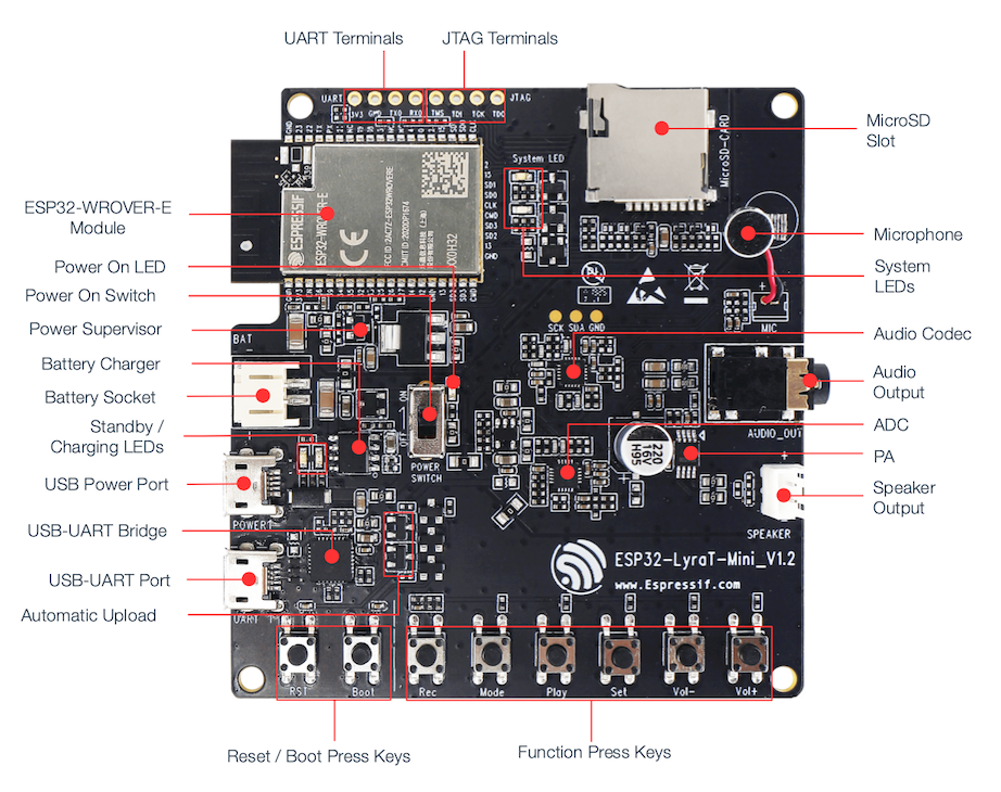
https://docs.espressif.com/projects/esp ... layout.png according to this image, I only have access to UART terminals and JTAG
How to connect mcp23017 with lyraT mini v1.2 board

Re: How to connect mcp23017 with lyraT mini v1.2 board
Those things are NC in the sense that they aren't connected inside the module, as they're used for PSRAM. I think the Lyra-Mini has test points for the internal I2C bus (labeled SCL/SDA/GND), perhaps you can hook the MCP up to that?
Re: How to connect mcp23017 with lyraT mini v1.2 board
Thank you for your valuable reply. I see that above the audio coded there are 3 gold circles - SCK, SDA and GNDThose things are NC in the sense that they aren't connected inside the module, as they're used for PSRAM. I think the Lyra-Mini has test points for the internal I2C bus (labeled SCL/SDA/GND), perhaps you can hook the MCP up to that?
I don't see SCL, are they both same?
Thanks again!
Re: How to connect mcp23017 with lyraT mini v1.2 board
According to AI:
 SCK is not the same as SCL
Even though the gold pad on your LyraT‑Mini is labeled SCK, it is NOT the I²C clock (SCL).
Instead:
 SCK = I²S Bit Clock (BCLK)
Used by the audio codec (ES8311) for digital audio.
 SCK ≠ I²C Clock (SCL)
I²C SCL is completely different electrically and functionally.
Is this right?
Thanks!
-
lbernstone
- Posts: 1133
- Joined: Mon Jul 22, 2019 3:20 pm
Re: How to connect mcp23017 with lyraT mini v1.2 board
Those test points in the middle are going to the I2C bus that runs the ADC and CODEC, not I2S. ChatGPT does not know how to read a schematic...
An alternative would be to set up a new I2C bus using pins 12 and 13 (TDI & TCK), which appear to be unused if you aren't running jtag.
An alternative would be to set up a new I2C bus using pins 12 and 13 (TDI & TCK), which appear to be unused if you aren't running jtag.
Re: How to connect mcp23017 with lyraT mini v1.2 board
Hello,
I managed to solder the 3 gold pads on my LyraT Mini v1.2 board. With a multi meter I confirmed that the pins are not shorted.
I have a breadboard that is supplied with 3.3V via another IC HW-131. I connected the ground from GND I2C and GND from battery as a common ground in the breadboard.
The breadboard has the MCP23017 IC, GND, SDA and SCK are provided from I2C to the MCP chip.
I wanted to make sure the the SDA / SCL / GND pins are correctly soldered or not. Is there some logic I can ask the AI to write that tells me that the pins are giving the right output. The reason for asking this is because I connected the 4x4 keypad but it is not able to detect the key presses - it thinks that some pins are already pressed. Moreover, this is the first time I soldered, so there is a good chance I would've messed something up.
I am using SD card play sample project and that seems to be working fine, I can hear the audio through the speakers. If I would have messed up the solder, then I wouldn't be able to hear the audio right?
I've attached images
- hw_131_3_3_V.jpeg (217.56 KiB) Viewed 405 times
- gold_pads_solder.jpeg (287.02 KiB) Viewed 405 times
- common_ground.jpeg (319.71 KiB) Viewed 405 times
Re: How to connect mcp23017 with lyraT mini v1.2 board
Attaching illustrated pinout for MCP23017
And the keypad
And the keypad
- Attachments
-
- keypad.jpeg (280.55 KiB) Viewed 405 times
-
- mcp23017_pinout_illustration.png (729.27 KiB) Viewed 405 times
-
lbernstone
- Posts: 1133
- Joined: Mon Jul 22, 2019 3:20 pm
Re: How to connect mcp23017 with lyraT mini v1.2 board
You should be able to run the Wire (aka I2C) scanner and see the device at the correct address on the bus (looks like you have it set to 0x20), along with the other devices connected to the bus (I don't know their addresses offhand). The mcp23107 isn't the most complicated of devices, but you'll still likely want to use a library of some sort (Arduino / ESP-IDF) so that you don't have to write your own decoder.
Re: How to connect mcp23017 with lyraT mini v1.2 board
Summary: I2C Issue and Fix
The Problem
The MCP23017 I/O expander (for the keypad) and the ES8311 audio codec both needed to share the same I2C bus (GPIO 18/23) on the LyraT Mini board.
What We Discovered
MCP23017 worked perfectly BEFORE audio_board_init() using the native ESP-IDF I2C driver
After audio_board_init(), using ESP-ADF's i2c_bus_read_bytes/i2c_bus_write_bytes gave garbage data (always read 0xB2 regardless of what was written)
Root Cause
We dug into ESP-ADF's i2c_bus_v2.c and found the bug on line 92:
.device_address = addr >> 1, // ESP-ADF shifts the address RIGHT
ESP-ADF expects an 8-bit I2C address (left-shifted with R/W bit), but we were passing a 7-bit address (0x21). So:
We passed: 0x21
ESP-ADF calculated: 0x21 >> 1 = 0x10 (WRONG device!)
The Solution
We found that ESP-ADF exposes i2c_bus_get_master_handle(port) which returns the native i2c_master_bus_handle_t.
The fix:
Let audio_board_init() create the I2C bus normally
Get the native handle: i2c_bus_get_master_handle(I2C_NUM_0)
Add MCP23017 using native API: i2c_master_bus_add_device(bus, &cfg, &mcp23017_dev)
Use native functions: i2c_master_transmit() / i2c_master_receive()
This allows both the audio codec (via ESP-ADF) and MCP23017 (via native driver) to share the same I2C bus without conflicts, each using their preferred API.
We are writing our own code - not using the UncleRus library.
We initially attempted to integrate the UncleRus mcp23x17 component, but it caused conflicts with ESP-ADF's i2c_bus library (both tried to manage the I2C bus, leading to crashes).
Our current implementation is minimal custom code:
This is just ~20 lines of code that directly uses the native ESP-IDF I2C master API, which integrates cleanly with ESP-ADF's audio board without any library conflicts.
Here's how mcp23017_dev is initialized in mcp23017_init():
The key insight is:
i2c_bus_get_master_handle(I2C_NUM_0) - ESP-ADF function that returns the native bus handle created by audio_board_init()
i2c_master_bus_add_device() - Native ESP-IDF function that adds our MCP23017 to the existing bus and gives us a device handle
This way we "piggyback" on the I2C bus that the audio board already created, rather than trying to create our own conflicting bus.
The Problem
The MCP23017 I/O expander (for the keypad) and the ES8311 audio codec both needed to share the same I2C bus (GPIO 18/23) on the LyraT Mini board.
What We Discovered
MCP23017 worked perfectly BEFORE audio_board_init() using the native ESP-IDF I2C driver
After audio_board_init(), using ESP-ADF's i2c_bus_read_bytes/i2c_bus_write_bytes gave garbage data (always read 0xB2 regardless of what was written)
Root Cause
We dug into ESP-ADF's i2c_bus_v2.c and found the bug on line 92:
.device_address = addr >> 1, // ESP-ADF shifts the address RIGHT
ESP-ADF expects an 8-bit I2C address (left-shifted with R/W bit), but we were passing a 7-bit address (0x21). So:
We passed: 0x21
ESP-ADF calculated: 0x21 >> 1 = 0x10 (WRONG device!)
The Solution
We found that ESP-ADF exposes i2c_bus_get_master_handle(port) which returns the native i2c_master_bus_handle_t.
The fix:
Let audio_board_init() create the I2C bus normally
Get the native handle: i2c_bus_get_master_handle(I2C_NUM_0)
Add MCP23017 using native API: i2c_master_bus_add_device(bus, &cfg, &mcp23017_dev)
Use native functions: i2c_master_transmit() / i2c_master_receive()
This allows both the audio codec (via ESP-ADF) and MCP23017 (via native driver) to share the same I2C bus without conflicts, each using their preferred API.
We are writing our own code - not using the UncleRus library.
We initially attempted to integrate the UncleRus mcp23x17 component, but it caused conflicts with ESP-ADF's i2c_bus library (both tried to manage the I2C bus, leading to crashes).
Our current implementation is minimal custom code:
Code: Select all
// MCP23017 device handle (native ESP-IDF)
static i2c_master_dev_handle_t mcp23017_dev = NULL;
// Simple register write
static esp_err_t mcp23017_write_reg(uint8_t reg, uint8_t value)
{
uint8_t data[2] = {reg, value};
return i2c_master_transmit(mcp23017_dev, data, 2, 100);
}
// Simple register read
static esp_err_t mcp23017_read_reg(uint8_t reg, uint8_t *value)
{
esp_err_t err = i2c_master_transmit(mcp23017_dev, ®, 1, 100);
if (err != ESP_OK) return err;
return i2c_master_receive(mcp23017_dev, value, 1, 100);
}Here's how mcp23017_dev is initialized in mcp23017_init():
Code: Select all
static esp_err_t mcp23017_init(void)
{
    // Step 1: Get the native I2C bus handle from ESP-ADF
    // (audio_board_init already created this bus for the codec)
    i2c_master_bus_handle_t bus = i2c_bus_get_master_handle(I2C_NUM_0);

    // Step 2: Configure the MCP23017 device
    i2c_device_config_t dev_cfg = {
        .dev_addr_length = I2C_ADDR_BIT_LEN_7,
        .device_address = MCP23017_ADDR,  // 0x21 (7-bit address)
        .scl_speed_hz = 100000,           // 100 kHz
    };

    // Step 3: Add device to the bus - this creates the device handle
    esp_err_t err = i2c_master_bus_add_device(bus, &dev_cfg, &mcp23017_dev);

    // Step 4: Configure MCP23017 registers for keypad
    mcp23017_write_reg(MCP23017_IODIRA, 0xF0);  // GPA0-3 outputs, GPA4-7 inputs
    mcp23017_write_reg(MCP23017_GPPUA, 0xF0);   // Pull-ups on inputs
    mcp23017_write_reg(MCP23017_OLATA, 0x0F);   // Columns HIGH initially
    ...
}i2c_bus_get_master_handle(I2C_NUM_0) - ESP-ADF function that returns the native bus handle created by audio_board_init()
i2c_master_bus_add_device() - Native ESP-IDF function that adds our MCP23017 to the existing bus and gives us a device handle
This way we "piggyback" on the I2C bus that the audio board already created, rather than trying to create our own conflicting bus.
Who is online
Users browsing this forum: PetalBot and 2 guests